
One of the benefits of running the IBM i is the ability to partition up the system and have instances of isolated IBM i running without having to spend lots of money on new hardware and software. The licenses which you have purchased on the hosting system can be used within the hosted system so no need to go out and purchase additional licenses for that Development system you want to run.
We need to micro partition our hardware resources to allow us to gain the most benefit out of the boxes we own as we do not want to waste precious resources on LPAR’s that may only use a fraction of a CPU most of the time yet need access to one or maybe even 2 CPU’s occasionally. We do a lot of development and testing of our HA products so we need the ability to simulate a number scenarios that customers run under such as different OS levels etc. This means we need to test across a number of systems. IBM i hosting IBM i allows us to do that cost effectively, especially for our size of organization.
In this post we are going to show you how we can add a new hosted partition to our existing setup. The system we are testing with currently runs a hosted partition and all of the resources are allocated between the two systems, so we are going to need to move some resources from the existing setup and reconfigure so when the system restarts the resources allow all of the LPAR’s to activate. As this is the second LPAR we have already gone through and set up some important configurations that allow the use of the network through a bridge (IBM used to allow Host Ethernet Adapter configuration in previous Power systems but not any longer). Setting up the bridge network capability requires a couple of profile settings and IBM i configuration changes
First of all we need to set the Virtual Ethernet Adapter assigned to the hosting LPAR to allow bridging, this is done via the profile used by the Hosting LPAR. Use the options to drill down to the Ethernet Virtual Adapter settings.
Note: We set the bridge capability using Dynamic Partitioning and the Virtual adapter settings, this is a similar interface. Once set, we did notice that it cannot be unset now we have the LPAR’s all up and running?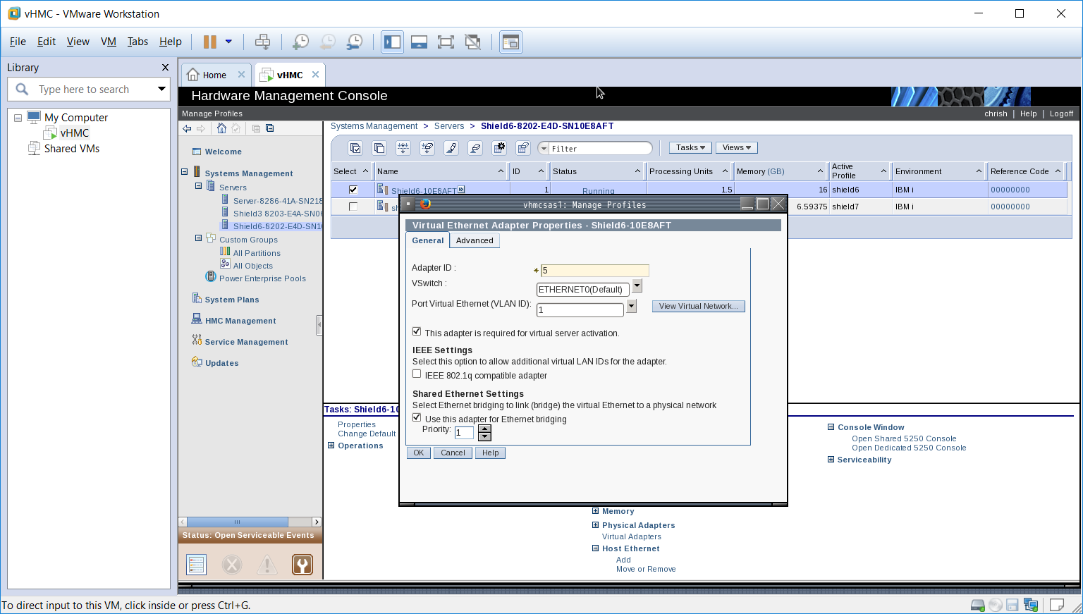
The setting you are interested in is the Use this adapter for Ethernet bridging. This is only required to be set on the Hosting LPAR, do not set this on the Hosted LPAR’s Ethernet adapter.
If you were unable to set this via Dynamic partitioning you may have to restart the hosting LPAR for the new setting to take effect (we had a few challenges getting this all to work).
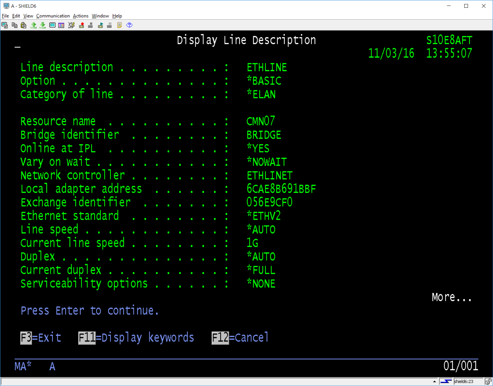
The hosting LPAR needs to have the Ethernet line description changed to add the bridge identifier in our case we used ‘BRIDGE’.
We also needed to create a new Ethernet line description, we simply called this ‘VIRTUAL’ the resource name was derived by identifying the resource which is generated when we set up the bridge capability for the Hosting LPAR. It is a type 268C not the 576F which is actual Ethernet adapter in our case. The following screens show the resource page and the configuration we created for the new line.

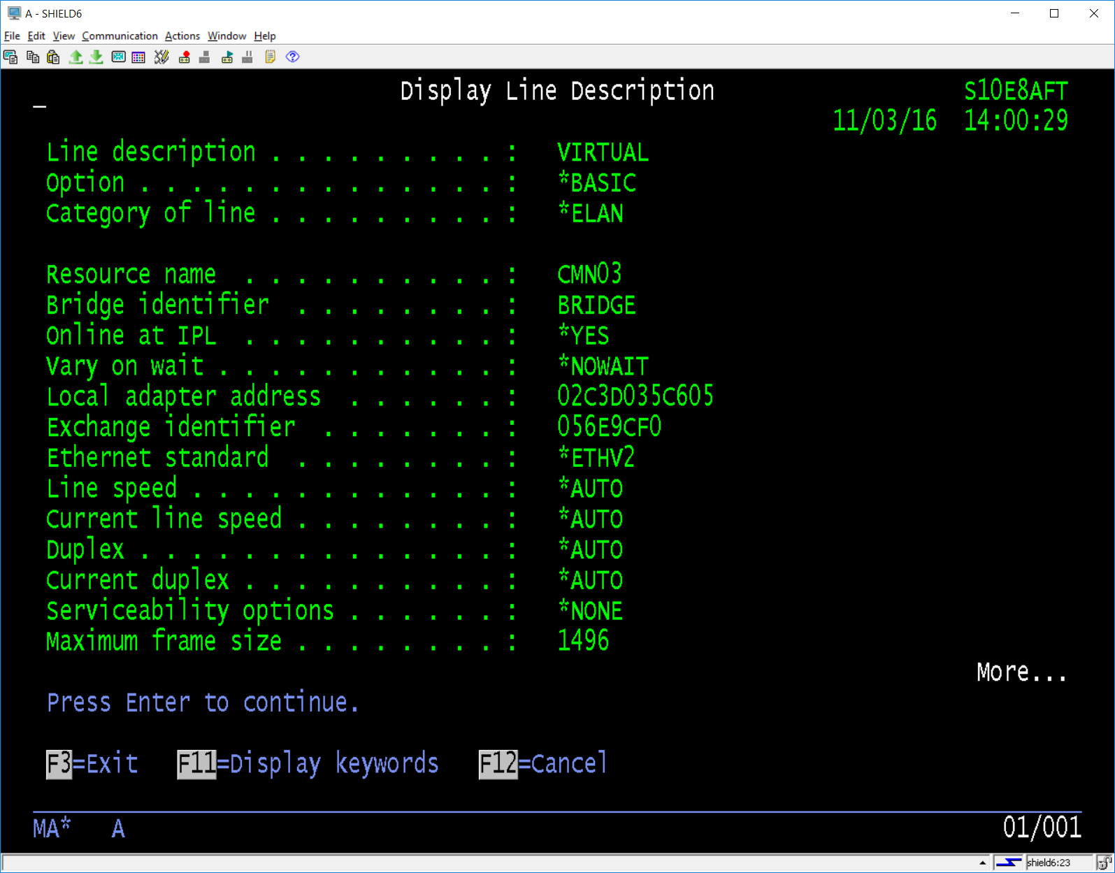
Once created we could vary on the ‘VIRTUAL’ adapter ready for use by the Hosted LPAR.
Next we needed to move some of the resources which would allow us to create a new LPAR. The memory allocated to the Hosting LPAR would be reduced to allow the new Hosted LPAR. This requires the profile for the Hosting LPAR be changed plus because we did not want to shut down the LPAR to move the resources we again used the Dynamic Partition capabilities.
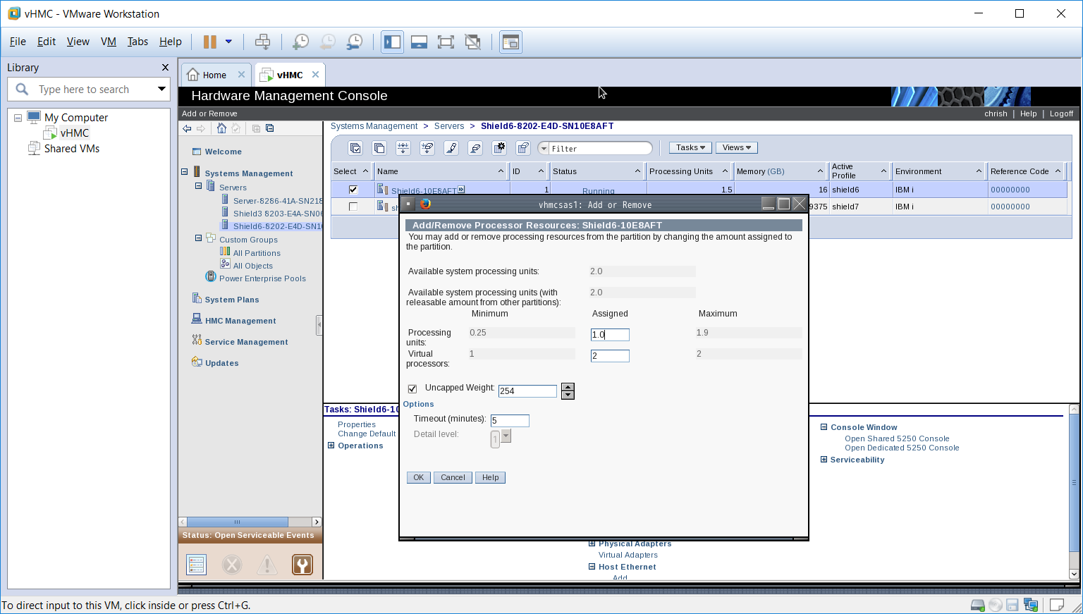
First we will remove 0.5 of the assigned processor from the Hosting LPAR.
Now we will remove 4GB of memory.
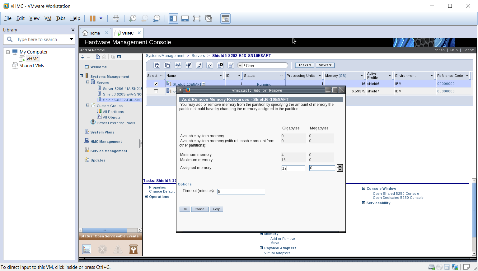
This is how the running LPAR now looks, as you can see the processor and memory assigned to the LPAR has been changed. But if we re-IPL the system without changing the profile, the system will try to allocate the existing configuration which means the resources will not be available to our new LPAR when it tries to start up. To fix this we have to amend the profile for the system via the manage profiles option selecting the hosting LPAR’s profile (in our case shield6).
First update the required Processor.

Now update the required memory.
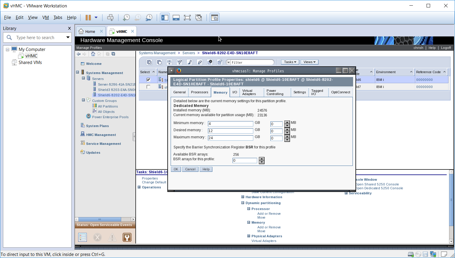
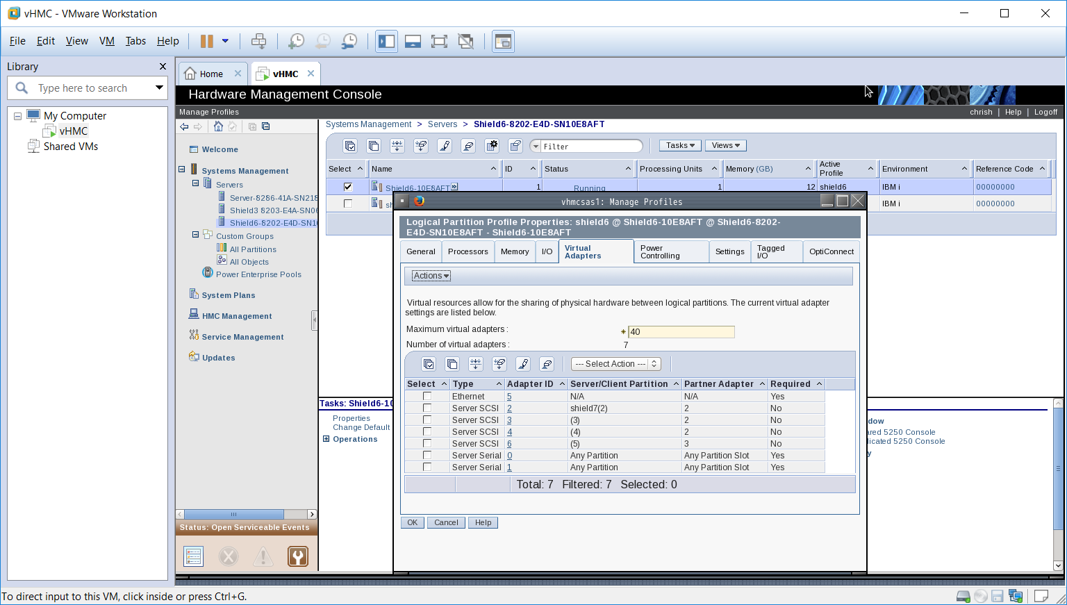
Save the changes to the profile before moving onto the next step. Here we are going to configure a new LPAR which is going to be run, we have already decided the processor and memory configuration to use the resources we removed from Hosting LPAR so the rest is pretty easy. Before you go further identify the virtual adapter that we need for the SCSI connection that is used for the DASD links etc. In our case we have already assigned the ID 2 to the previous LPAR, so we will use ID3 for this LPAR, also notice is automatically assigned the Partner Adapter ID as 2 even though noting is attached to it yet. We can manipulate the creation sequence of the Adapters to ensure these match up, if they don’t you will have to adjust these ID’s to ensure they match up.
The creation of a new LPAR is done form the server list not the list of LPARs on the server. Select the server option and then select the server you are going to build on.

Open the configuration link and drill down to Create Partition and select IBM i. the following display will show.

First fill in the partition name, this is an important parameter which we will use later to configure the *NWSD on the Hosting LPAR. In our case we following a naming convention and simply called it shield8. Enter a name you want and press next, you will see the following screen.
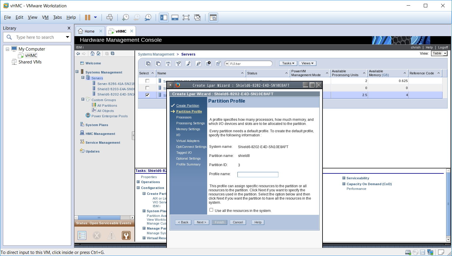
Note: The profile name and the LPAR name are different parameters, we used the same name for each but you could change to suit your needs.
Enter a suitable name for the profile, you may want to append the name with ‘prf’ so in our case we would have entered ‘shield8prf’. Press next and you will see the following screen.

As we mentioned above we want to be able to share the CPU across a number of LPAR’s so we leave the Shared option checked. Click next for the following screen.
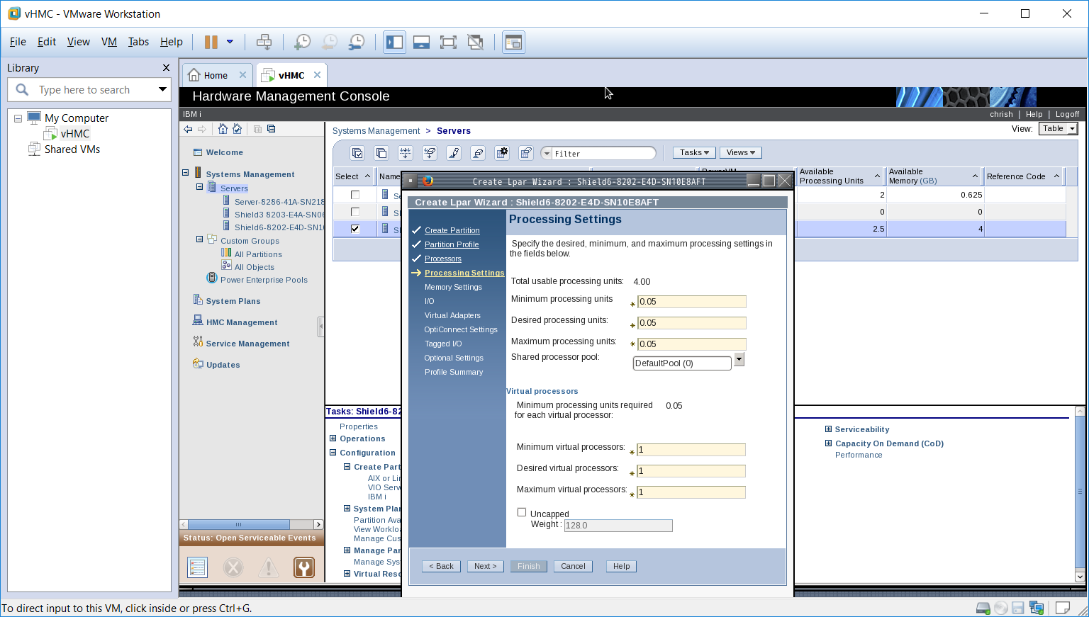
The system has allocated the minimums allowed, we want this LPAR to be assigned 0.5 of a processor, there is information around which describes all of the settings and how you should set them up. In our instance I am going to set a minimum or 0.05, Desired 0.5 and a maximum of 2.0 (that’s the most we have licensed) we will also use the Processor pool we built when we set up the original system. The setting up of a pool stops the irritating messages about unlicensed processor use even if you only define the correct amounts to your LPAR’s (see previous post for more details). The Virtual processor settings we will use are minimum 1, desired 2 and maximum 4, again plenty of information on how to calculate these settings to get the best results. We want any unused processor to be moved to other LPAR’s if not needed on the current LPAR so we set the uncapped setting and give it a weight for resource allocation in our case we just used the default of 128.

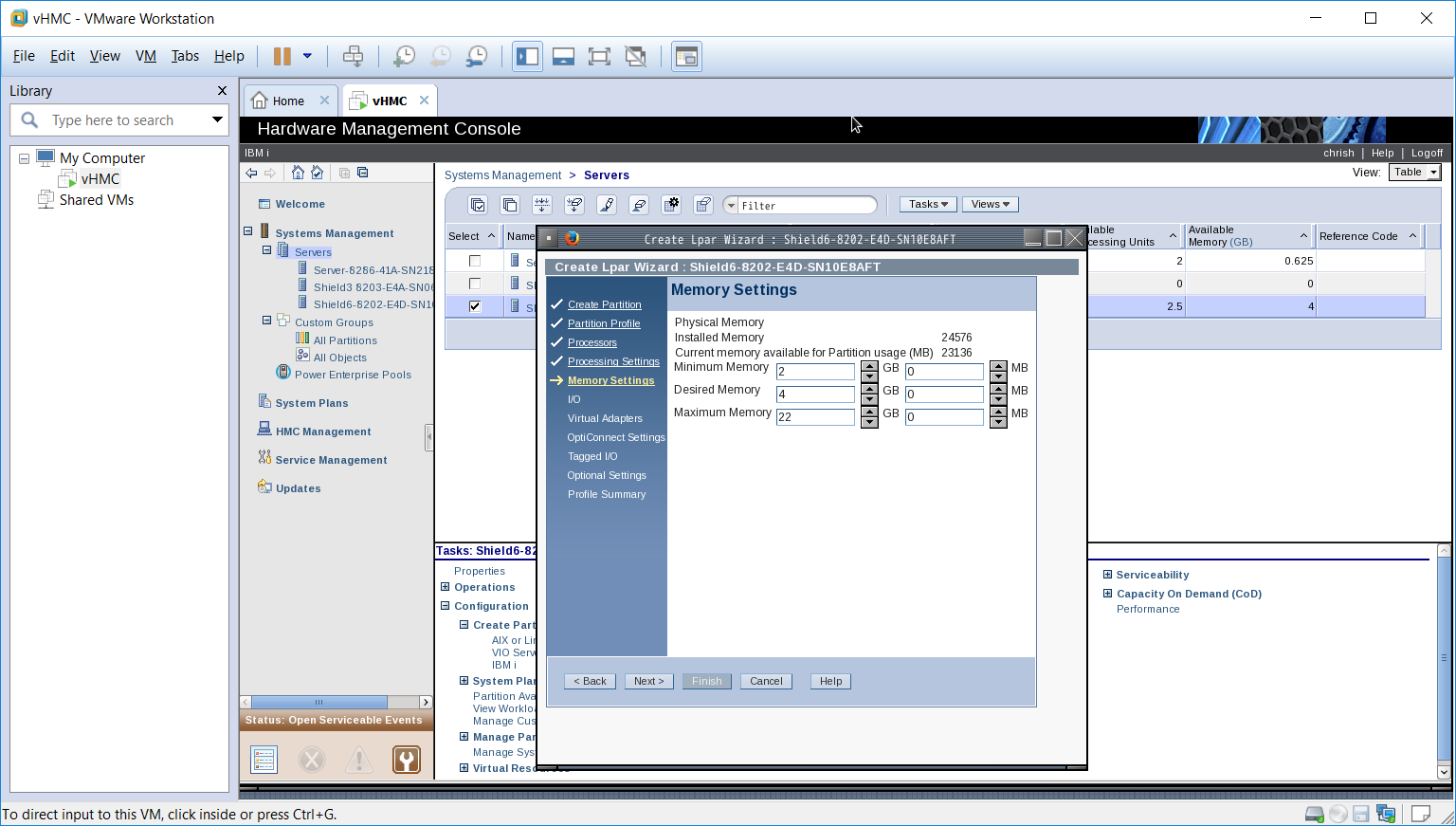
Click next where we allocate the memory, we used minimum 2Gb, desired 4GB and maximum 22GB. The memory can therefore be moved around the LPAR’s by the system.
We are not going to used dedicated hardware, this is a hosted LPAR which is going to use all of its resources from that shared by the Hosting LPAR so press next twice to get to the following screen.

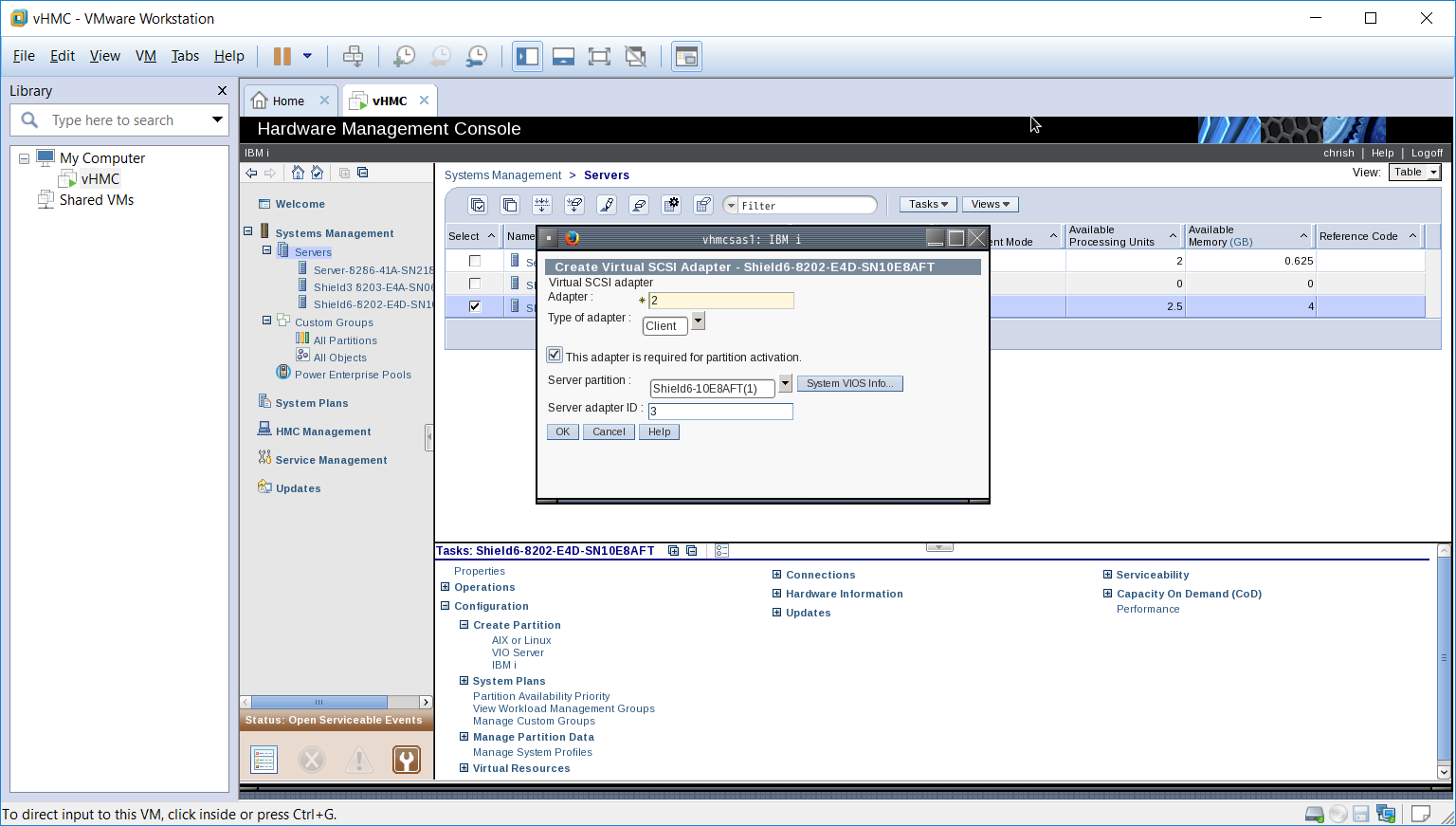
This is where we will configure the virtual adapters we want to use. As you can see the default Server Serial adapters are configured, we could add a client Serial adapter for such things as terminals etc but not in this instance. We want to configure the SCSI adapter and make sure it ties up with the SCSI server configuration we have on the Hosting LPAR, in our case we will create a Client SCSI adapter with an ID of 2 that points to the Server SCSI dapter with an ID of 3 on the Hosting LPAR. We also want to ensure this adapter is available for Hosted LPAR start up. Make sure you get the ID’s correct at this stage to avoid a lot of head scratching later when you cannot start the LPAR.
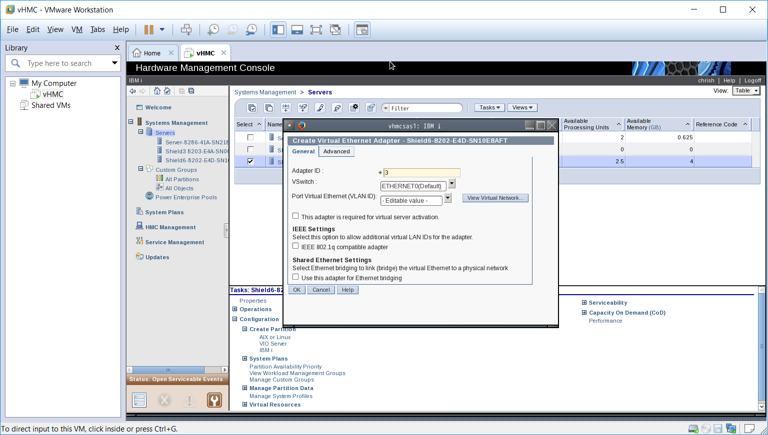
Next add the Ethernet virtual adapter, no special requirements re bridging on this adapter, its all done on the Hosting adapter configuration
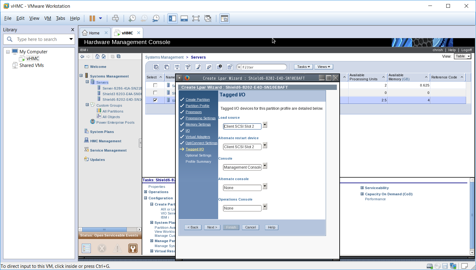
Press next twice, we do not have opti-connect installed so cannot configure it. You should see the following screen. We have set tagged IO to use the SCSI adapter for both the Load Source and the Alternate restart device. If you do not set these values when you try to start the LPAR you will see an error stating the Load source cannot be found.
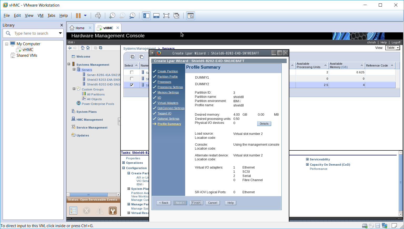
Click next twice (we do not need any additional settings), you will now see a summary of the settings, just run your eye over them to make sure they look Ok and click finish to create the LPAR profile.
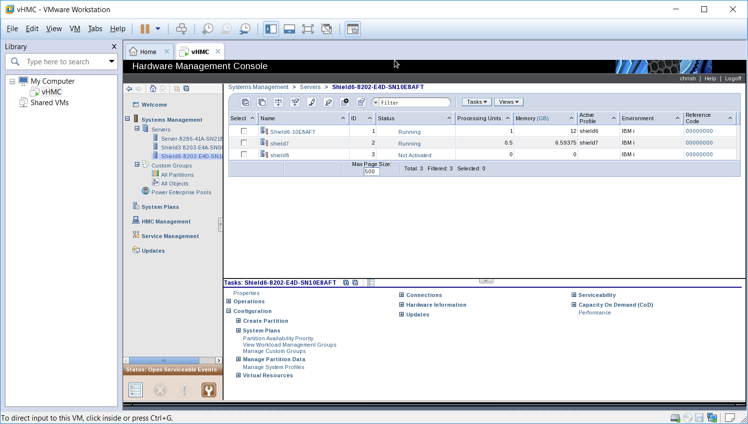
You can now click on the server to see the new LPAR has been configured as shown below.
Now all we need to do is create the IBM i objects which are required to allow the installation of the OS etc. First we will create a *NWSD object, the following screens show how we created one for our shield8 configuration. This is carried out on the Hosting LPAR (shield6) and needs to be carried out using a User profile with sufficient authority.
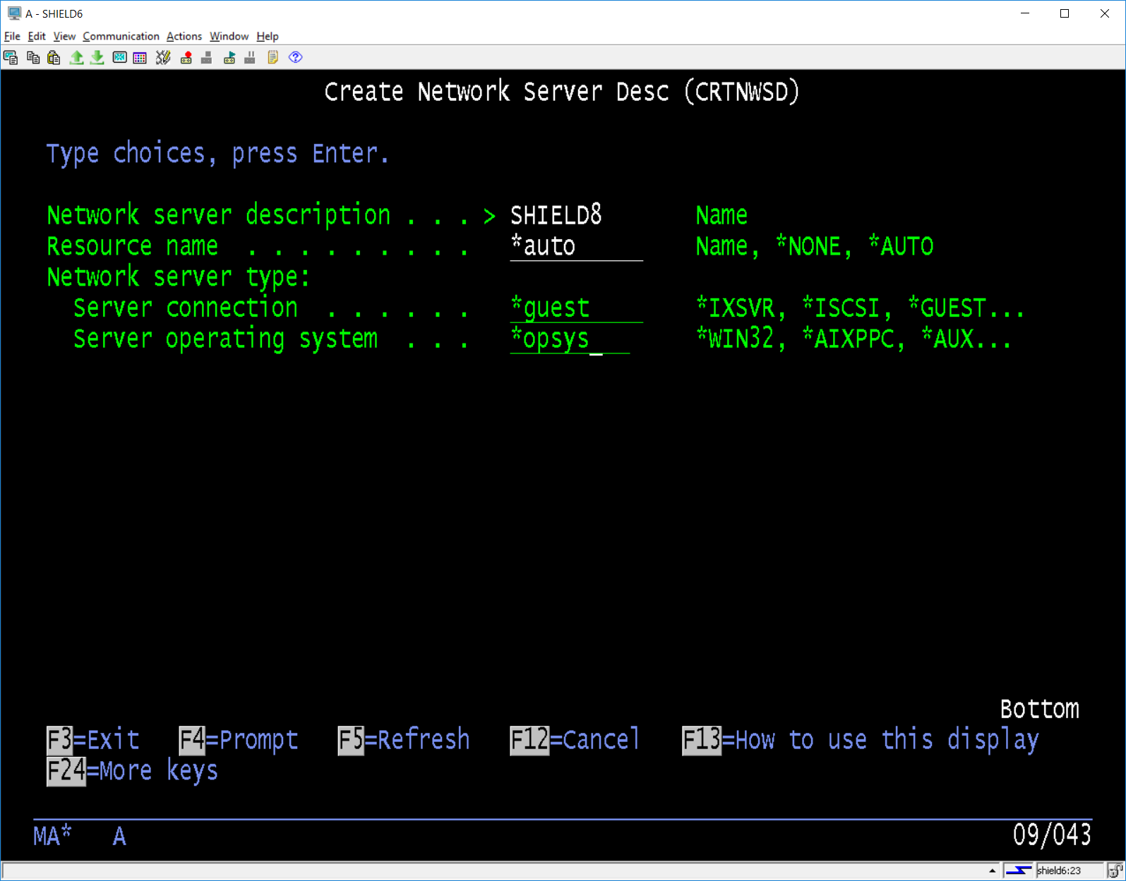
We set the resource name to *AUTO so the partition name could be used to match up with the resources generated by the profile. The following screen we changed the Partition parameter to match the partition name we gave it on the first screen (not the profile name).
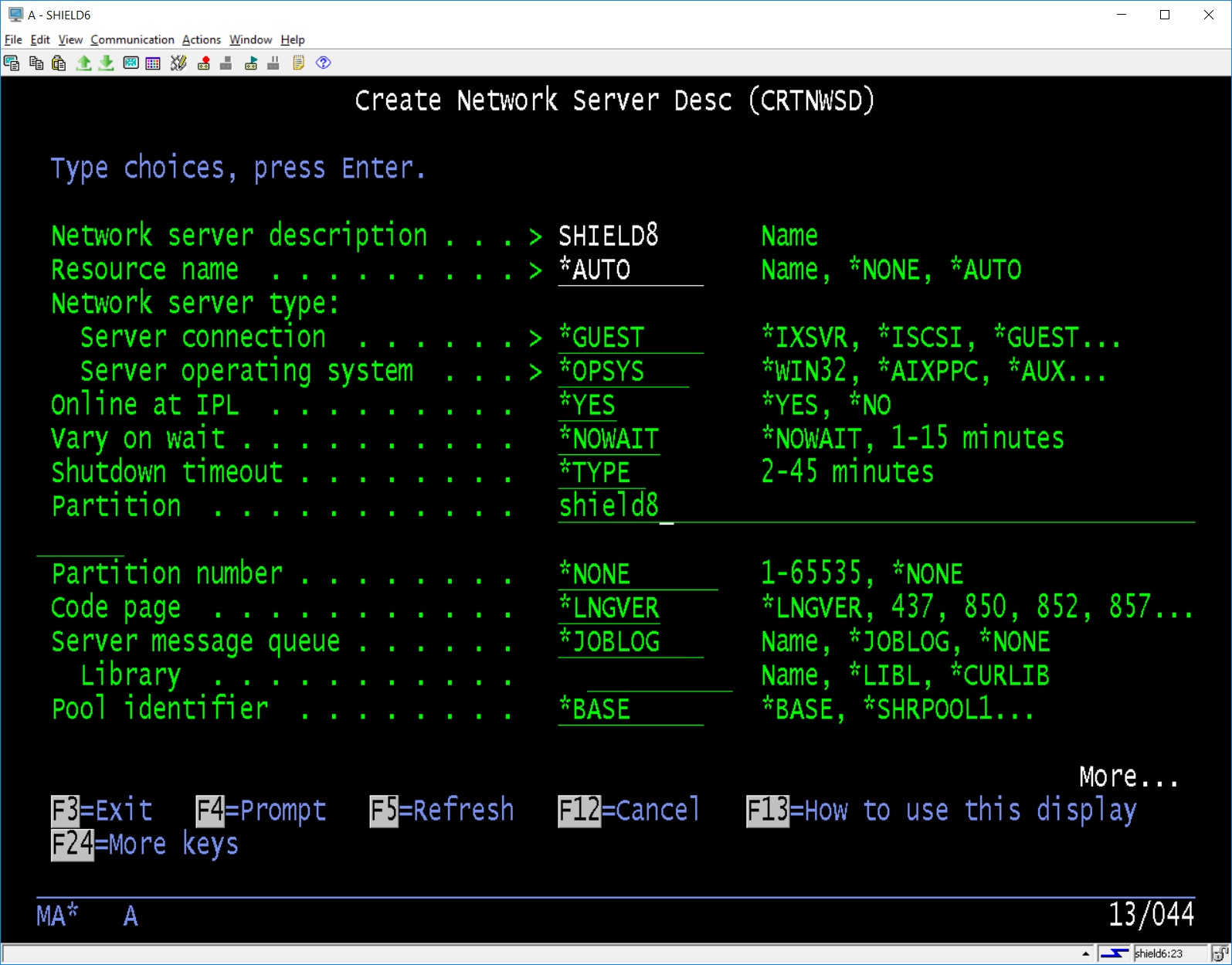
The only other parameter we are interested in is the power control, we set this to *NO.
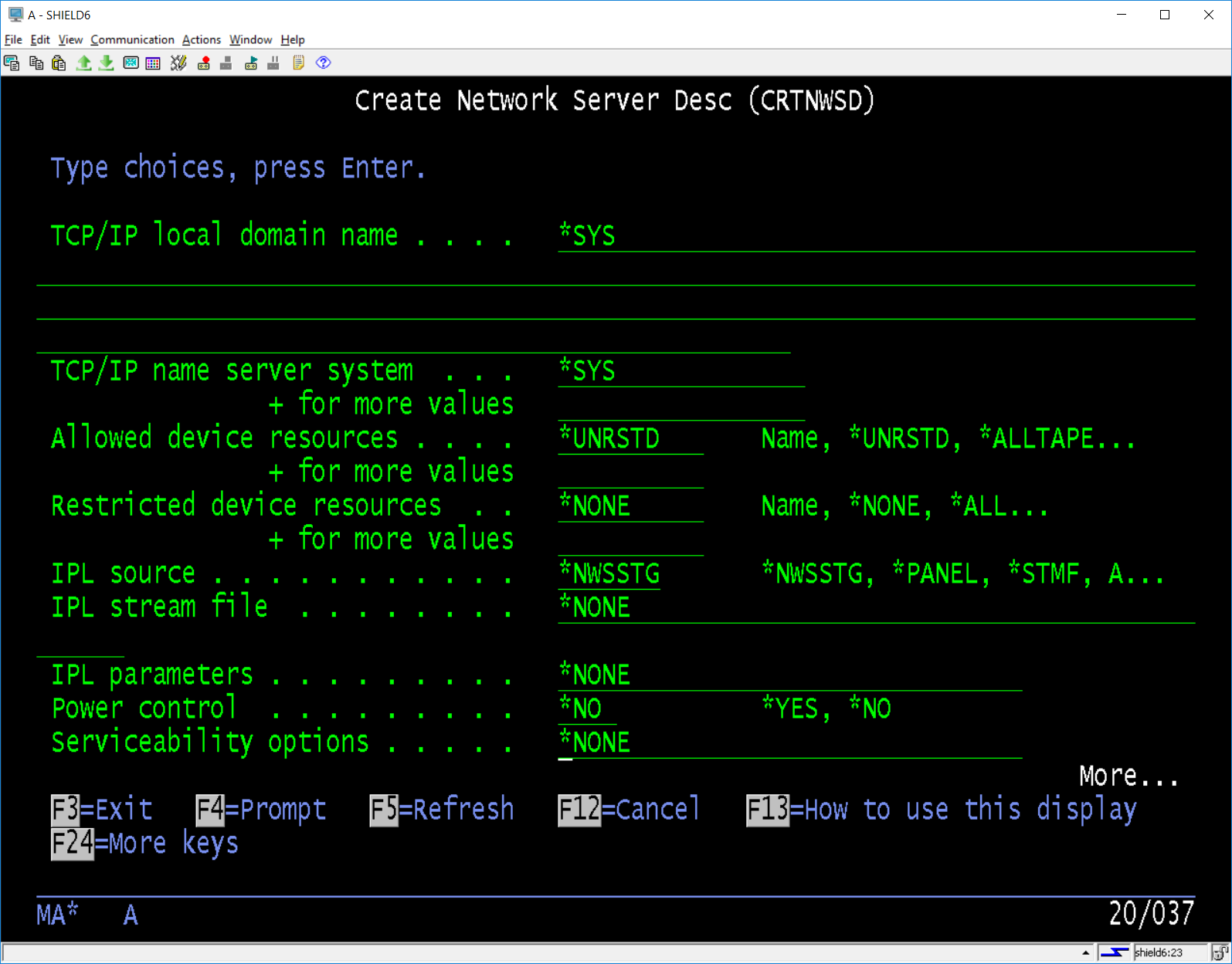
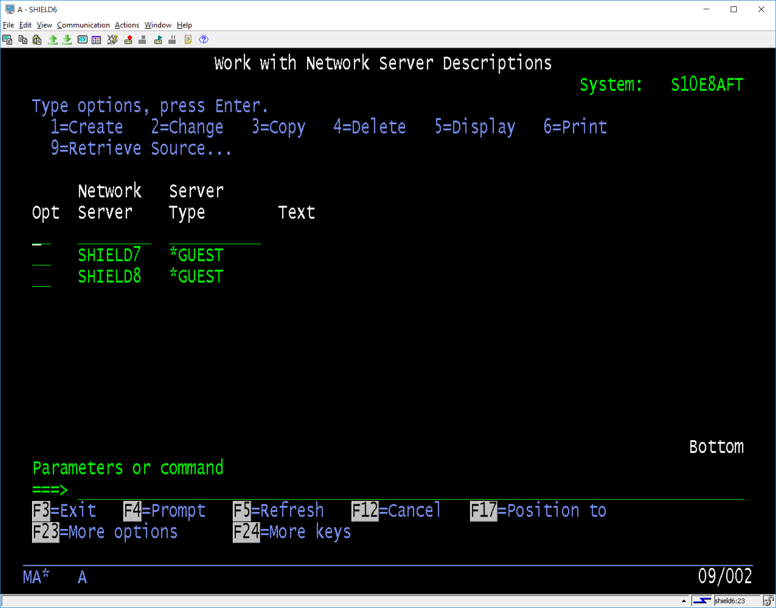
You can add a description if you want then press enter to create the NWSD. Below shows the new *NWSD object is created.
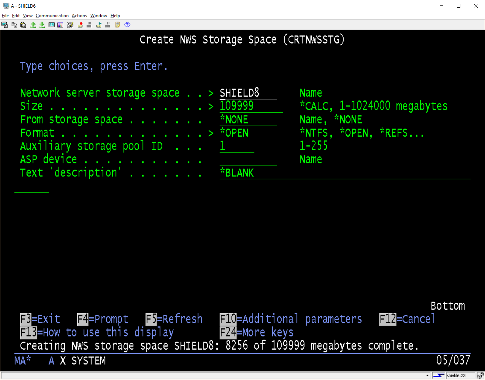
Now will create a *NWSSTG object that we will connect to the *NWSD object, this is the DASD that will be used by the LPAR, in our case we are going to create a *NWSD of 100GB, this can be altered later if required using the available commands.
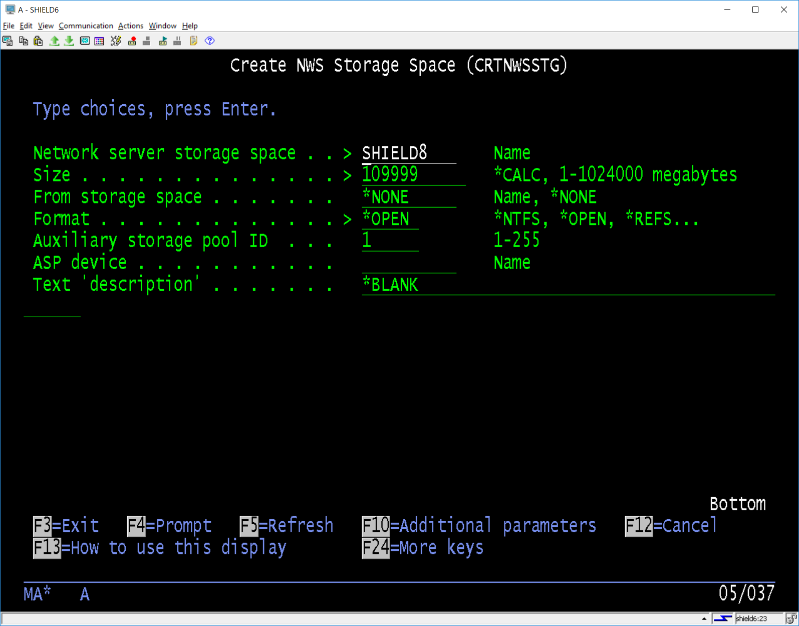
The above command takes sometime to complete so go get a coffee, we are almost finished. You will see messages across the bottom of the screen as the space is allocated such as below.
Note: Allocating the space removes it from the available DASD completely. It does not allocate the DASD as you add more objects to the Hosted LPAR. Allocating significantly more than you need could expose your system to a DASD shortage later on the Hosting LPAR.
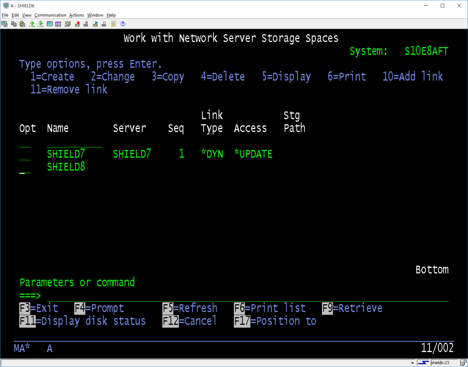
Now that we have allocated the space we need to link this to the *NWSD object, we used the option from the list of *NWSSTG objects to link to the *NWSD object SHIELD8.
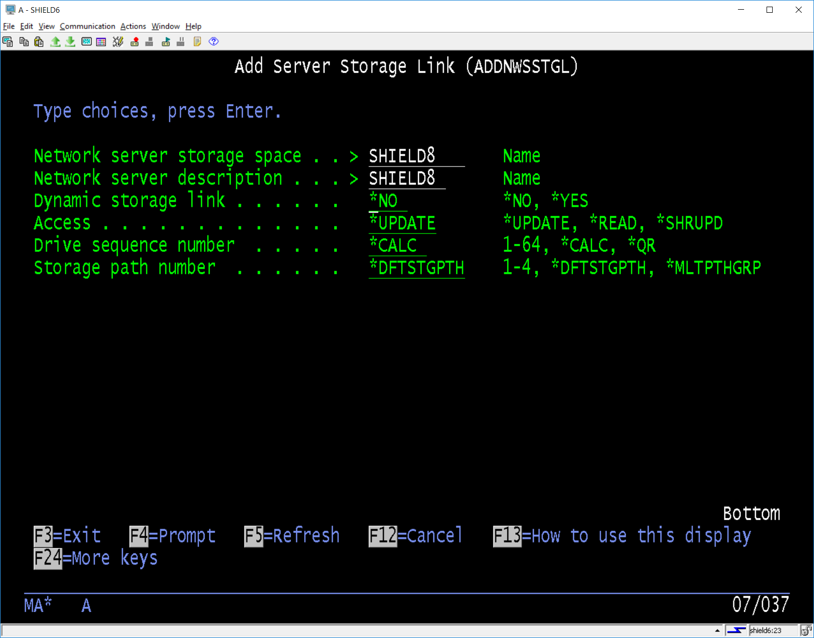
Use option 10 to add a link to the selected NWSSTG, this will show the following screen. We can leave the Dynamic Storage to the default of *NO as it is only required if storage is *IXSVR and will be changed to *YES automatically.
Once linked the list of NWSSTG objects is updated to show the link we have just added to the object.

Now we can start the *NWSD and the installation of the OS can begin. If the *NWSD fails to go ACTIVE you have a problem in your configuration somewhere.

That’s it you now have an IBM i LPAR hosted by another IBM i LPAR, you can use the CD’s to install the OS you want to run and configure as you like. The License keys that are generated for your hosting LPAR will work in the Hosted LPAR assuming it’s the same OS level (7.3 etc.) As always IBM does put some restrictions on the OS levels that will run on the hardware etc, these restrictions need to be understood before you embark on his project.
If you the above is beyond you but you would like to have a hosted LPAR on your existing system, give us a call to discuss your requirements.
Chris…